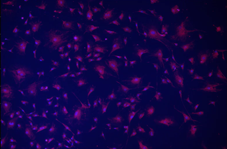
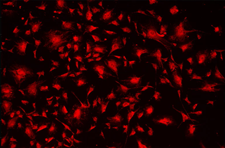
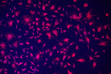
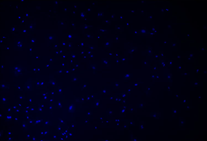
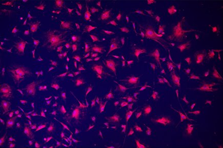
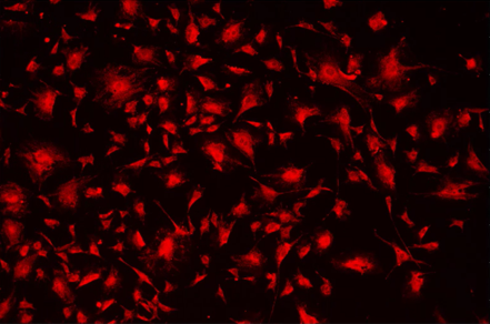
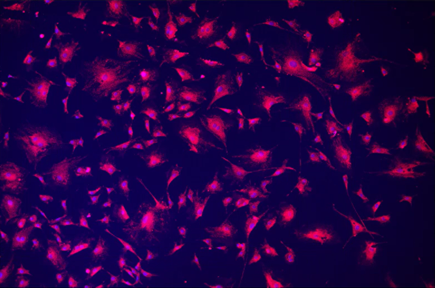
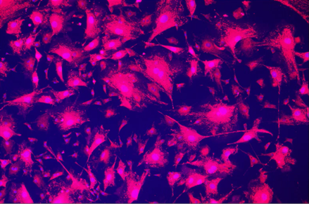
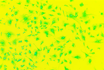
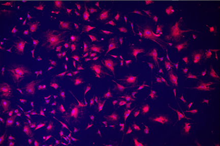
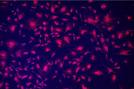
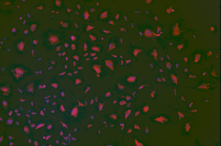
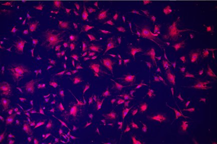
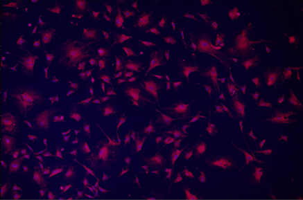
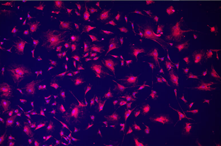
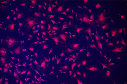
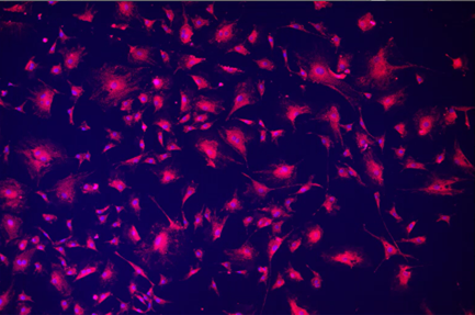
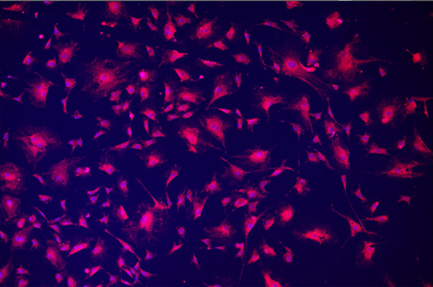
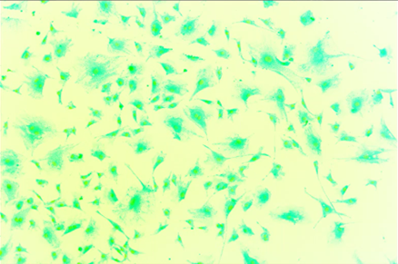
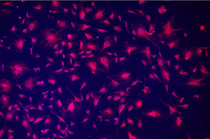
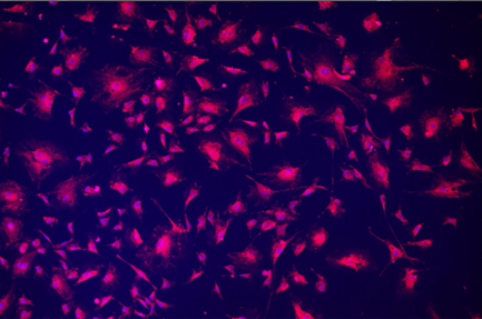
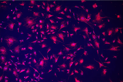
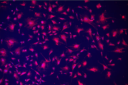
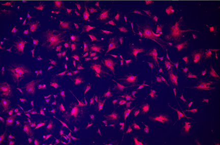
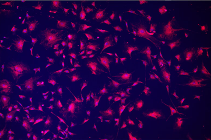
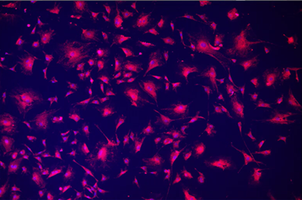
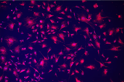
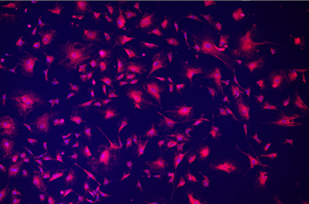
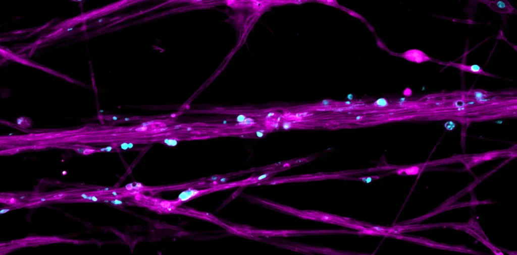
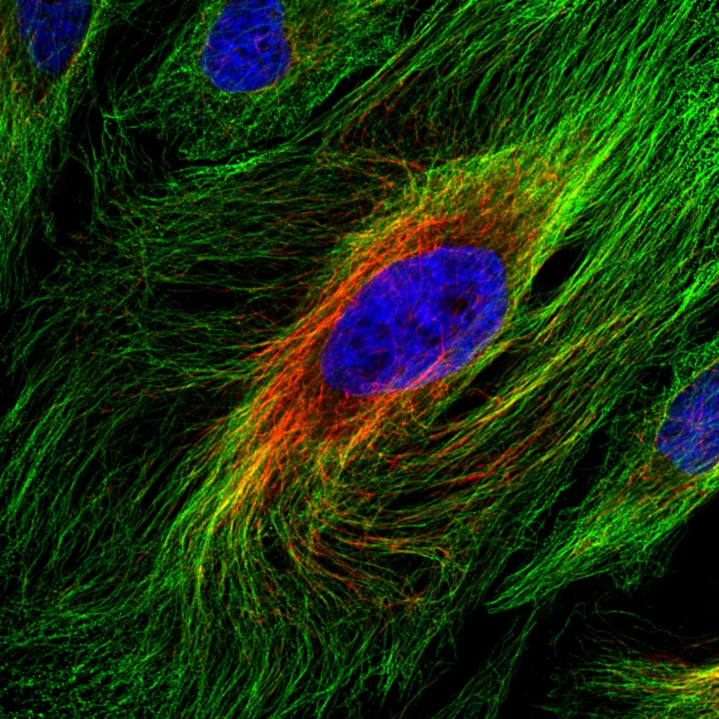
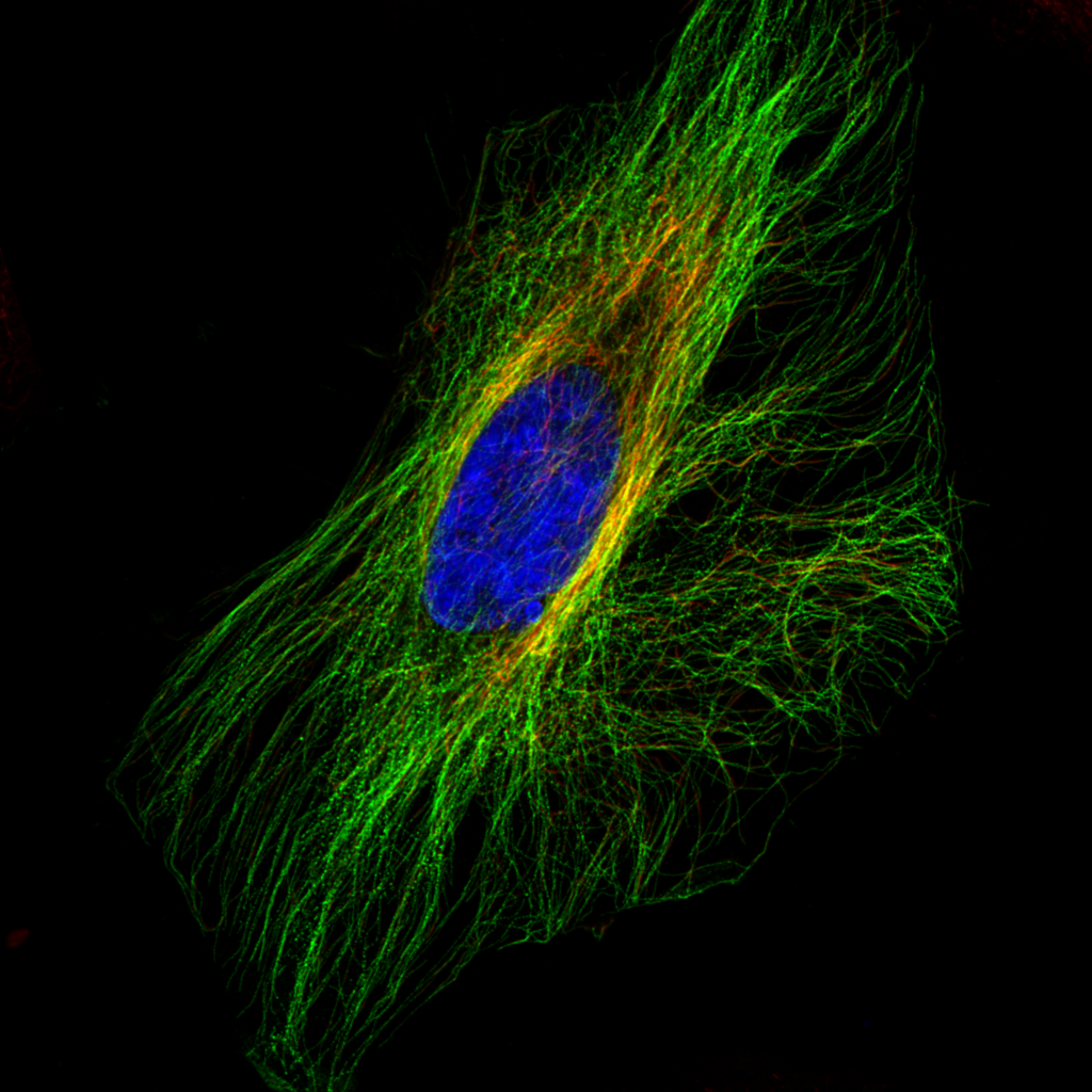
| Add (Image x Image) | Added image’s own DAPI component. Might be useful for emphasizing nuclei/filaments while still showing other elements. |
 |  |
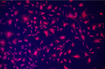
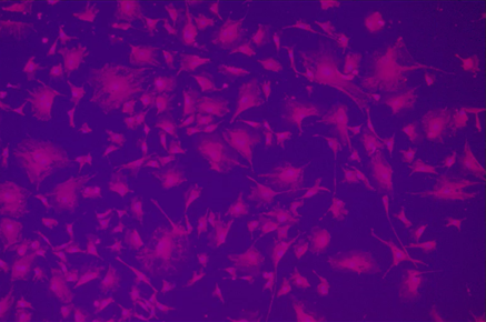
| Subtract (Image x Image) | Subtracted image’s own DAPI component after splitting RGB into separate channels. DAPI was subtracted from blue (subtracting from RGB resulted in a black image). |
 |  |
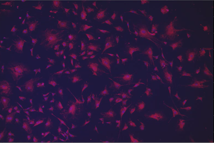
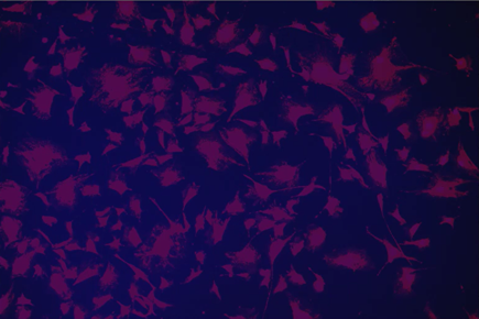
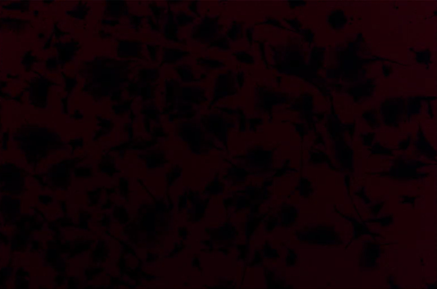
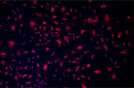
| Multiply (Image x Image) | Multiplied by image’s own DAPI component, resulted in a dimmed version of the DAPI channel with only blue in the histogram. May be useful for isolating components while also denoising. |
 |  |
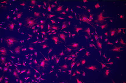
| Divide (Image x Image) | Divided image by its own DAPI channel, which resulted in an entire image of pixels with RGB (0,0,1). Applied Auto Contrast afterwards to emphasize the result. Not sure this option has many applications. Suppose you could divide by a grid to get gridlines? Images have to be the same size to use divide. |
 |  |
| Minimum | Takes the minimum of the input images. Used the FITC component of the original image, which resulted in the blue component being removed. May be useful for a timelapsed sequence of images to highlight changes between frames. |
 |  |
| Maximum | Takes the maximum of the input images. Used a 20X portion of the original image, resulting in both 10X and 20X cells appearing. |
 |  |
| Covariance | Finds covariance between images of each pixel. Probably best for grayscale images. Used the DAPI channel of the original image as the other input, which resulted in high FITC signal areas having lower covariance of red. Output is a float image with values for each color channel. |
 |  |
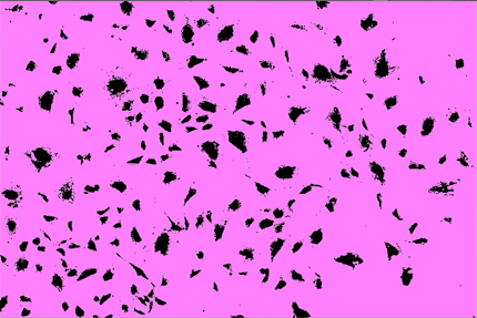
| Mask Image | Removes parts of an image not covered by a binary. Detected background and operation removed cells. |
 |  |
| Remove Shading | Performs a shading correction on the first image specified by the second image. Worked like Divide but with higher resultant intensity (did not increase contrast here) when correcting original image by its own DAPI component. |
 |  |
| Add (Image x Constant) | Adds specified constant to R, G, and B values of each pixel. Used 50 here (meaning a pixel with 10/0/75 would become 60/50/125). It ended up desaturating the image, if higher values are used the image becomes closer to white. |
 |  |
| Subtract (Image x Constant) | Subtracts specified constant from R, G, and B values of each pixel. This image had 0 for the green channel, so subtracting resulted in a negative value which showed up as a black screen. However, applying Abs to the result made the green values positive and the image visible. Subtracted 50 and then used Abs here. |
 |  |
| Multiply (Image x Constant) | Multiplies R, G, and B values of each pixel by the specified constant. Used 5 here. |
 |  |
| Divide (Image x Constant) | Divides R, G, and B values of each pixel by the specified constant. Used 10 here. |
 |  |
| Clip | Sets the R, G, and B values of each pixel to fall in between the specified bounds. Values within the bounds are unchanged, values lower than the min are set to the min, and values higher than the max are set to the max. Used bounds of 10 and 80, which would set a pixel with 113/0/61 to 80/10/61. |
 |  |
| Constant Value | Sets R, G, and B values of each pixel to the specified constant, which just results in a uniform gray. Not sure this has many applications. Used a constant of 50. |
 |  |
| Abs | Takes the absolute value of each pixel’s RGB values. Useful if you have negative values after using something like Subtract (see above), has no effect if values are already all positive. |
 |  |
| Invert | Sets RGB values to (max allowed intensity)-(original value), which inverts image colors. |
 |  |
| Exp | Each pixel’s RGB value is set to (specified base)^(original value). Results in very large RGB values. If original value causes result to exceed 32-bit float limit (on the order of 10^38), value is set to infinity and pixel is black. Used base 2 here-anything larger caused large parts of image to overflow. |
 |  |
| Inv | Each pixel’s RGB value is set to its reciprocal (1/original value). Used auto contrast on the result to enhance visibility, but result is still quite dim. |
 |  |
| Log | Sets each pixel’s RGB value to log of specified base (original value). Used the default base of 10 here. |
 |  |
| Pow | Sets RGB value of each pixel to (original value)^(specified exponent). The default value of 2 did a good job at separating cells/sharpening the image, but noise reduction should still be used. Highly recommend this one! |
 |  |
| Sign | Computes the sign of each intensity value for each channel for every pixel (1 if positive, 0 if 0, -1 if negative). Since all R/B values were positive and all G values were 0, the result is a uniform magenta for the example image. |
 |  |
| Greater | Compares intensity values from 2 channels and outputs a value of 1 if A > B or 0 if A ≤ B. Compared red to blue here. LUTs were adjusted to make result visible. |
 |  |
| Greater or Equal | Compares intensity values from 2 channels and outputs a value of 1 if A ≥ B or 0 if A < B. Compared blue to red here so it is approximately the inverse of the Greater example. LUTs were adjusted to make result visible. |
 |  |
| Equal | Compares intensity values from 2 channels and outputs a value of 1 if A == B or 0 if A != B. Compared red to blue here. LUTs were adjusted to make result visible. If input order is reversed, the same pixels are visible in the blue channel. |
 |  |
| .Not E-qual | Compares intensity values from 2 channels and outputs a value of 1 if A != B or 0 if A == B. Will probably make most of the image {1} values. Compared blue to red here. LUTs were adjusted to make result visible. If input order is reversed, the same pixels are visible in the blue channel. This node will produce the inverse of Equal. |
 |  |
| Blend | Blends a foreground image and a background image using a third image as weight. All images must have the same bit depth, pixel dimensions, and calibration. Used 3 images of cells here. |
 |  |
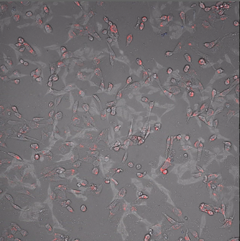
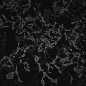
| Conditional | Takes 3 channel inputs: a True layer, a False layer, and a Condition layer (shown). If the intensity value of the Condition layer is 0, the output of that pixel will be the corresponding pixel from the False layer. If the intensity value of the Condition layer is not 0, the output will be the corresponding pixel from the True layer (a brightfield image unlike the other 2 layers in this example so it is more visible). All inputs must have the same dimensions. |
 |  |

